Why We Need Chemical Deactivation
Gas chromatography (GC) is, undoubtedly, a very powerful separation technique. Thanks to the high efficiency of capillary columns, GC can separate very complex samples with ease and in increasingly shorter times. Almost any volatile organic compound and permanent gas can be sampled via a clever range of introduction techniques and analysed by GC. We also enjoy a wide range of stationary phases, and manufacturers are still developing new chemistries to tackle the most challenging problems.
So, it would seem that GC has reached its peak. Everything is done: we have the hardware, the chemistry, the efficiency, the know-how. We inject the sample and we get sharp, symmetrical, perfectly resolved peaks every time, something like this:


Figure 1: GC-MS chromatogram of 17 fatty acids on a J&W DB-WAX UI column.
Column: Agilent J&W DB-WAX UI 30m × 0.25mm, 0.25μm
| Peaks: | ||
| 1. Methane | 7. Isovaleric Acid | 13. Heptanoic Acid |
| 2. Acetone (solvent) | 8. Valeric Acid | 14. Pyruvic Acid |
| 3. Acetic Acid | 9. 4-Methylvaleric Acid | 15. Octanoic Acid |
| 4. Propionoic Acid | 10. Hexanoic Acid | 16. Nonanoic Acid |
| 5. Isobutyric Acid | 11. 4-Methylhexanoic Acid | 17. Decanoic Acid |
| 6. Butyric Acid | 12. 2-Ethylhexanoic Acid |
Oh and, of course, GC columns last for 800 injections or more before they show signs of needing a replacement.
Wait, then why is it that my chromatogram last week looked like this?


Figure 2: GC-MS chromatogram of 17 fatty acids on a J&W DB-WAX column.
Column: Agilent J&W DB-WAX UI 30m × 0.25mm, 0.25μm
The separation above is a mixture of underivatised organic acids on two different WAX columns. What has gone wrong? A lot of factors in a GC system that can produce distorted peaks: faulty connections, dead volumes, poorly cut or installed columns. But the awful peaks in my chromatogram are due to something else: as the acidic analytes flow through the GC system, they undergo chemical interactions with active sites on a variety of exposed surfaces. These sites promote additional retention mechanisms that delay the elution of the solutes, resulting in distorted peaks.
Organic acids are some of the most challenging substances a GC analyst must deal with on a regular basis, but they are not the only ones: alcohols, amines, sulphur compounds, and a wide range of polar, chemically complex and highly reactive analytes that cause tailing peaks, split peaks, inlet contamination, and column degradation. One of the hottest topics in GC is the efficient removal, or at least the deactivation, of chemically active sites throughout the GC system, in order to facilitate the analysis of reactive compounds.
Where is the Problem?
We all know that inlet liners are designed to provide a clean environment for the sample to vaporise upon injection. We also know that liners packed with glass wool plugs enhance evaporation efficiency and can trap non-volatile solutes to prevent column contamination. However, if the liner or the glass wool are not properly deactivated, the presence of chemically active silanol groups can result in loss of analyte due to adsorption on the surface. Experience shows that only highly deactivated liners should be used for labile and chemically active analytes, and they need to be replaced often for best results. Typical effects of an active liner can be seen in the following figure:
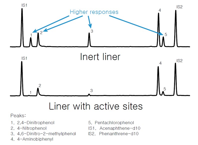

Figure 3: GC chromatography of 7 polar compounds using (top) an Agilent Ultra Inert deactivated liner and (bottom) non-deactivated liner.
Poorly cut capillary columns can expose the damaged surface of the fused silica tubing. Non-volatile and highly active solutes can interact with these sites and produce distorted peaks. The effect is often cumulative, as residues build up with each injection. Overheating the column, or exposing it to large volumes of aggressive solvents, will over time strip the stationary phase and expose more of the underlying active surface.
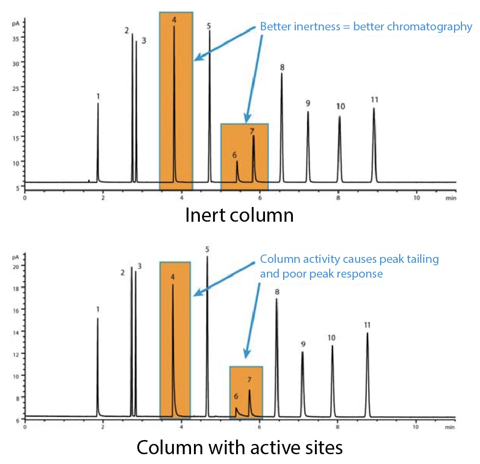

Figure 4: Comparative GC-FID analysis of a Grob test mix on (top) Agilent Ultra Inert deactivated capillary column and (bottom) poorly cut capillary column with residual silanol surface groups exposed.
Even though the analyte residence time in the GC detector is very short, many critical components can have active metal surfaces that are likely to interact with the solutes. This is especially true of mass spectrometer detectors, where solute compounds can adsorb on components such as the repeller and ion lenses.
The same can be said of ferrules, gold seals (in Agilent systems), and ancillary hardware elements. In short, every component of the GC which comes into contact with the sample could contribute to peak distortion. Moreover, it is sometimes difficult to identify the source of the problem:


Figure 5: Detail of GC-MS analysis of drugs of abuse for complete flow path inertness comparison.
In an ideal GC system, the whole sample flow path would be chemically deactivated to minimise or eliminate the occurrence of active sites.
What to Do
Traditionally, we have followed a number of steps to make the sample flow path as inert as possible:
-
- Use high-quality gas, free of contaminants, moisture and oxygen.
-
- Use gas filters to actively decrease the risk of column damage and reduce background noise.
-
- Regularly replace dirty, worn out, or damaged consumables such as syringe needles, septa, ferrules, and inlet seals. Use high-quality spares and ensure that solvent compatibility and upper-temperature limits are met.
-
- Change the liner and gold seal when discolouration or build-up of non-volatile residues are apparent.
Beware that glass wool packing in the upper half of the liner can be physically damaged by the needle with each injection, accelerating the appearance of active sites.
-
- Choose a column that has been tested for inertness.
Use a magnifying glass to examine the column ends for chips and burrs after making every cut, and take care to install the column at the recommended depth according to manufacturer recommendations.
-
- Use high-quality jets with FID and thermionic detectors. Clean the detector regularly, or as soon as symptoms of contamination appear.
For mass spectrometry detectors (MSD), use tune reports to look for evidence of contamination. Use an inert ion source where possible.
Unfortunately, all these GC components degrade with each new injection, and the familiar chromatographic problems eventually reappear. A more permanent solution must come from using improved, perhaps as yet unexplored, inert materials in the construction of GC hardware and columns; of from treating the surfaces of existing materials to deactivate reactive sites.
Agilent UI Range
In 2008, Agilent took a first step towards the construction of a completely inert GC flow path with the introduction of J& W Ultra Inert (UI) columns. These were the first columns that consistently delivered inertness and low bleed, batch after batch.
Ultra Inert is a proprietary deactivation treatment that deposits a protective coating on glass, fused silica, or metal surfaces. The thickness of the coating can range from about 10nm to several micrometres, depending on the dimensions of the component to be deactivated and its intended application.
Based on the success of UI columns, Agilent has extended the UI range to inlet liners, fittings, ferrules, retention gaps, and detector consumables. With the addition of inert ion sources for MSD systems, the IU range now provides inert components for the whole sample flow path:
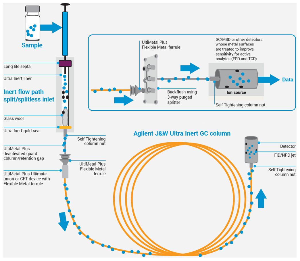

Figure 6: Agilent Inert flow path solutions.
Ultra Inert Inlet Liners
Agilent Ultra Inert inlet liners are certified to provide low surface activity and reproducible sample vaporisation, even for chemically active analytes. The latest generation of UI liners moves away from traditional glass wool packing, in favour of more reproducible glass frits:


Figure 7: Detail of Ultra Inert low frit split liner.
These high purity frits, which also undergo the UI deactivation treatment, reduce the need for frequent replacement. They are particularly suitable for SVOC and pesticide analysis but will improve chromatography for any difficult analyte, including amines in drugs of abuse.
Ultra Inert Gold Seals
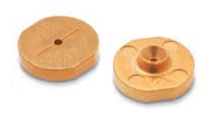

Figure 8: Detail of Ultra Inert gold seals.
UI deactivation, on top of the characteristic gold plating, reduces analyte adsorption while ensuring a leak-free seal with the column ferrule.
UltiMetal Plus Ferrules


Figure 9: UltiMetal Plus flexible metal ferrules.
UltiMetal Plus flexible metal ferrules complement traditional graphite, polyimide, and graphite/polyimide ferrules. UltiMetal Plus ferrules, however, are unique in having a deactivated surface.
Split/Splitless Inlet
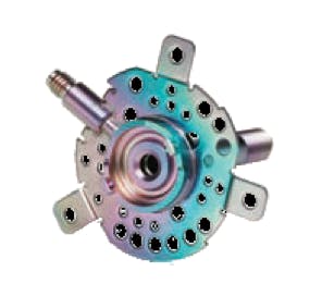

Figure 10: Agilent split/splitless inlet with UltiMetal surface treatment. Note the iridescent finish due to multilayer reflections on the UltiMetal inert coating.
Those sections of the split/splitless inlet that come in contact with the sample are treated with the same proprietary deactivation as Ultra Inert gold seals and UltiMetal flexible ferrules.
Ultra Inert Columns
GC column inertness is critical, as columns contribute the largest surface area within the GC flow path. Every Agilent J& W Ultra Inert GC column is rigorously tested to ensure consistently high inertness and low bleed.
Do you remember the two chromatograms at the start of this article? The “nice” one was obtained on a DB-WAX UI column, which has been treated to deactivate residual silanols and improve its inertness in front of acidic and basic solutes, without the need for derivatising the sample. The “ less nice” chromatogram was obtained by the same chromatographic method, on a DB-WAX column. This column has an identical WAX stationary phase, but it has not been deactivated, and the existence of silanols and other active sites is obvious.
Numerous applications have been developed to demonstrate that the stationary phase on both columns is the same. The following figure shows a “ head to tail” comparison of a lavender oil sample, analysed on DB-WAX and DB-WAX UI columns under identical conditions:


Figure 11: Head to tail comparison of GC-FID analysis of lavender oil sample on (top) J&W DB-WAX and (bottom) J&W DB-WAX UI columns.
Retention times, peak shapes and areas match remarkably well on both chromatograms, evidence that the stationary phase has not been affected by the UI treatment. The ability of UI-treated columns to preserve selectivity as compared to their untreated counterparts was critical to the introduction and approval of this technology. Ultra Inert columns have the same selectivity and USP G code as their non-UI counterparts, which implies that existing methods can be transferred to UI columns without the need for redevelopment and, crucially, without the need for method revalidation.
Besides improving peak shapes, Agilent found that UI deactivation improved the thermal stability of the stationary phase, reducing column bleed and effectively expanding its operating temperature range. The two chromatograms below show a Grob test mix analysed on two columns of identical dimensions, by the same chromatographic method:


Figure 12: Comparative GC-FID analysis of a Grob test mix on (top) Ultra Inert deactivated CP-Wax 52 CB and (bottom) non-deactivated CP-Wax 52 CB columns. Bot columns were baked at 250°C for 1 hour to assess thermal stability of the stationary phase.
The black (top) trace was acquired on a CP-Wax 52 CB column after having been baked at its maximum isothermal temperature for an hour. Peaks 4a and 4b (stereoisomers of 2,3-butanediol) show a reduced height and substantial tailing, caused by thermal damage to the stationary phase. The green (bottom) trace was obtained on a UI-deactivated CP-Wax 52 CB, baked under the same conditions. Peak shapes appear unaffected by the baking process.
The results obtained with DB-WAX UI were so successful that this became the leading column in Agilent’s WAX portfolio. Subsequently, Agilent rolled out the UI deactivation process to a whole range of columns, including HP and DB-1 ms UI, DB-5 ms UI, DB-624 UI, and others.
UI chemistry
What is Ultra Inert, and how is it applied to such a diverse range of components as liners, gold seals and columns?
Ultra Inert (UI) and the closely related UltiMetal (UM) and UltiMetal Plus are surface deactivation techniques. They are all based on chemical vapour deposition (CVD) of an inert layer on the surface of the treated components. Ultra Inert was developed for glass, fused silica and gold seals, whereas UltiMetal was specifically developed for stainless steel, although it can be successfully applied to glass and other surfaces.
The pieces to be treated are introduced in a large stainless-steel container, which is then sealed. The air inside the container is evacuated and replaced with a reagent gas. This gas will react with the surface of the components to deposit the desired deactivation layer. The container is then heated to several hundred degrees for several hours to allow the CVD reaction to take place. The thickness of the resulting layer depends on the chemistry and pressure of the reagent gas, the temperature, and the time of reaction. Different reagent gases result in deactivated surfaces with different chemical and physical properties. SiH4, for example, deposits an amorphous silicon coating. Gases like hexamethyldisiloxane (HMDSO) and tetraethylorthosilicate (TEOS) can be used to deposit a polymeric siloxane layer.
The UM treatment deposits a layer of metal atoms that bond directly to the substrate surface, filling pores and cracks, and resulting in a smooth and inert finish. Reagent gases used for this treatment are organometal complexes of aluminium or titanium, which yield a layer of Al2O3, TiO2 or other inert oxides directly bonded to the support. The thickness of the coating is in the order of several hundred nanometres, which gives the finished pieces a distinctive iridescence.
It is worth noting that UM-treated pieces can be bent and reshaped without compromising the protective layer. This is especially interesting for tubes, capillaries, ferrules, and similar components that must be connected and disconnected repeatedly. UI coatings, on the other hand, do not have this property. The deactivated coating is brittle and will break if is mechanically stressed.
Conclusions
Chemical inertness is critical inside the GC injection port, where labile analytes are prone to adsorption on exposed surfaces or degradation at high temperatures. Beyond the inlet, all flow path surfaces that may come into contact with the injected sample can contribute to analyte loss or degradation. This includes the analytical column, but also retention gaps, ferrules, seals and detector components.
Agilent developed a proprietary manufacturing process, known as Ultra Inert, which is used to produce inlet liners and gold seals with an improved deactivation coverage. The enhanced inertness improves analytical accuracy and reproducibility and reduces the need for frequent replacement of UI liners. The same deactivation technology has been applied to a range of analytical columns covering the most popular chemistries and dimensions. UI treated columns exhibit improved peak shapes for very polar, acidic, and basic compounds, as well as lower bleed and improved temperature stability. Improved peak shapes and bleed translate into lower detection limits, more reproducible chromatography, and longer column lifetimes.
Whilst column inertness is improved, stationary phase chemistry is unaffected by the UI deactivation. Every J& W Ultra Inert GC column is rigorously tested using probes with varying chemical characteristics to prevent polymer selectivity variations. This ensures that J& W Ultra Inert columns have the same selectivity as their non-UI counterparts, which in turn means that methods based on traditional stationary phases can be migrated to UI columns without altering method conditions and, crucially, without the need for method revalidation.

