
What makes a peak broad in gas chromatography
Sometimes troubleshooting a separation can rely on the end user to spot subtle clues in the chromatogram, and other times the visual clues can be much more obvious.
I like to include real world examples in my lessons as they more effectively illustrate the appearance of peaks and baselines that are not what they should be. This helps students fine-tune their "problem radar" and spot problems as they arise - accelerating experiential learning that can otherwise take months and years to accumulate.
what makes a peak broad in gas chromatography
I want to share some of the most common peak shape problems in gas chromatography in the hope that if you discover some of them in your own work, you can catch problems and solve them more effectively.
📋 Here you can find ✍
Example 1 - Peak Tailing

Illustration 1: Chromatograms showing deteriorating peak tailing effects.
This example shows two overlaid chromatograms where peak tailing is more pronounced (the blue chromatogram has peaks that tail more than the red chromatogram), but both suffer from the problem. Sometimes the peak tailing phenomenon can be more subtle and you may have to zoom in to see the problem. Tailing is measured using Tailing Factor (Tf) or Asymmetry Factor (As), and an asymmetry or tailing factor greater than 1.5 would indicate tailing is sufficient to investigate the problem.
Tailing can lead to a reduction in resolution between peaks, making integration (and therefore quantification) less accurate and reproducible - so we want to avoid this.
Peak tailing issues can be caused by many factors including (in order of priority that I would investigate the issue)
- Poor Inlet Column Cut - Column is irregularly cut or not cut at 90O to the column wall. Cut the column again (2-5 cm) and check the quality of the cut with a loupe or low-magnification microscope
- The column is incorrectly placed in the inlet - the end of the column is not at the correct height in the inlet. Check column placement (according to manufacturer's instructions)
- Polar or ionic analytes interact with “active” sites within the liner or column head. Use a fresh (deactivated) liner or cut 10-20 cm from the front of the column. Note that retention time windows may need to be adjusted slightly to account for small changes in peak retention times
While these are the main causes of peak tailing, there can be other issues, but checking and fixing the issues outlined here should resolve most issues. For more subtle issues, you can use the "Ask the Expert" feature within CHROMacademy to get help on your own individual issue.
Tailing doesn't always have to be so subtle, and I've shown an extreme example below where solvent peaks (present in trace amounts in the sample) show very poor peak tailing.
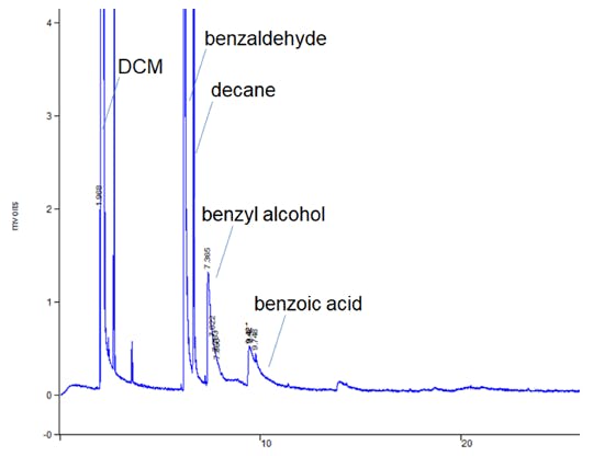
Figure 2: Pronounced peak tailing in a residual solvent GC method.
This example highlights a good tip when it comes to fixing tailing peaks. If ALL peaks are trailing within the chromatogram, the problem is physical (poor column cut/poorly positioned column) rather than chemical (secondary retention of polar analytes).
what makes a peak broad in gas chromatography
Example 2 - Peak Fronting
Can also be a very subtle phenomenon, but again can affect resolution, especially in very convoluted chromatograms, or reproducibility/accuracy of peak integration.

Figure 3: Subtle deformation of peak shape known as peak fronting.
In Figure 3 we again see two chromatograms that show a deterioration in peak fronting (blue more pronounced than red).
In many cases, the cause of peak fronting is GC column overload caused by injecting too much analyte mass. One must be aware that a GC column contains a very small amount of stationary phase, a 30 M column may contain only a few milligrams of stationary phase material depending on the film thickness, and so the phase can quickly become occluded by adsorbed analyte will flood forward in the column, resulting in excess analyte. This creates a concentration gradient which manifests itself as a peak "front" at the detector end of the column.
Almost always the trick is to reduce the amount of analyte going into the column, and the checks I would do in this case are (again in order of priority - which is influenced by the ease with which potential causes are checked and can be eliminated and probability);
- Check that the split setting is correct and that the split flow is at the correct flow rate (here I mean you need to check the instrument's split outlet with a gas flow meter!). Confirm or correct if necessary
- Check that the correct injection volume has been set within the method and that the correct syringe volume is being used. Most autosamplers rely on a stepper motor to control the injection volume, so a setting of 0.1μL with a 1μL syringe will produce a 1μL injection if a 10μL syringe was accidentally installed on the autosampler!
- Check the path length of the GC column used. Thicker stationary phase films can handle higher analyte loadings, and a 1 μm film can withstand much higher loading than a 0.1 μm film.
- Check the concentration of your sample. Usually a careful review of your sample preparation procedure compared to what was actually done during sample preparation. Check reagent strengths, glass volumes and volume settings on positive displacement pipettes!
Again, this is not an exhaustive list, but one that should cover many of the causes of analyte overload observed in the laboratory.
If you suspect that this overload is your problem, look at the detector responses and peak retention times, or overlay your chromatogram with a chromatogram that you know is less of a problem. Sometimes a "big picture" can reveal a big problem, as I showed in Figure 4.

Figure 4: Overlaying current and previous chromatograms can often help us see the bigger picture—and the obvious overload seen with the blue chromatogram.
Example 3 - Peak Splitting
A typical example is a peak with two crests or a "ragged" peak apex, and this effect can be very subtle, as shown in Figure 5. However, the impact on the reproducibility of peak integration (and hence peak area) can be large and indicate that the system is performing sub-optimally.

Figure 5: Subtle distortions in peak shape at peak peak and shoulder, which can be referred to as peak splitting.
To give you some "hope" in spotting these problems, I've shown in Figure 6 how bad the problem can get when peak splitting becomes a real problem, and this trace analysis highlights the problem well.

Figure 6: More peak splitting during this trace splitless analysis (top: bad chromatogram, bottom: good chromatogram). Note that retention times are given in seconds (s).
Peak splitting can be caused by both chemical and physical effects, similar to the peak tailing we saw in Example 1. Particular care should be taken when working in splitless injection mode as despite the name we call the injection technique Peak a split is more likely as I will explain below.
So, probable causes and remedies, in order of priority, are:
- Improperly cut column or occluded stationary phase at top of GC column
- Sealed stationary phase (i.e. phase has adsorbed non-volatile matrix material)
- Incorrectly positioned column in the GC inlet. As with the peak tailing issue, remake and check the column cut, ensure the column is positioned correctly in the inlet and trim 10-20 cm from the front of the column if necessary. "Physical" causes such as those described in points 1-3 are indicated when ALL peaks within the chromatogram are split. Where only certain analytes show the splitting behavior, chemical effects are much more likely
- Problems with sample diluent and/or initial oven temperature during splitless injection. With splitless injection, the analyte evolves more slowly from the inlet into the GC column, which of course would produce very broad peaks. To solve this problem, we use a lower initial oven temperature to "focus" the analytes using two phenomena - thermal focusing (the analytes condense on the stationary phase at a point in the temperature gradient between the hot inlet and the much cooler GC column in oven) and solvent focusing (more volatile analytes contained in the sample solvent condense into a film on the GC stationary phase, this film then evaporates to produce a narrow analyte band).In order for these processes to run correctly, several factors must be taken into account, which are described below:i) The initial oven temperature should be 20OC lower than the boiling point of the sample solvent. If the initial oven temperature is too high, broad and/or split peaks will occur since the higher, intermediate to higher boiling analytes will not condense efficiently in a narrow band on the stationary phase.ii) The chemistry of the stationary phase should match the polarity of the analytes and especially the polarity of the sample solvent. So if you try to perform a splitless injection on a wax column with hexane as the sample solvent, spit peaks will be generated.
what makes a peak broad in gas chromatography
I hope the information above can help you identify problems in your gas chromatography and, perhaps more importantly, troubleshoot the underlying causes quickly.
👩🔬 If you want to know other articles similar to What makes a peak broad in gas chromatography you can visit the Gas chromatography
Killer Gas Chromatography variables and other insidious ways to destroy your chromatography!

GC Inlet Maintenance

GC Carryover Problems

Reduction of instrument downtime

What is Gas Chromatography?

Factors Affecting Retention Time in Gas Chromatography

Principle and procedure of gas chromatography

Principle and applications of gas chromatography

Type of Gas Chromatography Detectors
You May Be Interested in: